

Micro - bends in fiber optic cables can significantly degrade the performance of fiber optic networks, leading to signal attenuation and potential data transmission issues. As a trusted Otdr Equipment supplier, I am here to share with you how to use Otdr Equipment to detect these micro - bends effectively.
Understanding Micro - bends in Fiber Optic Cables
Before delving into the detection process, it's essential to understand what micro - bends are. Micro - bends are small, localized deformations in the fiber optic cable that occur due to various factors such as improper installation, mechanical stress, or environmental conditions. These bends can cause light to leak out of the fiber core, resulting in signal loss. The impact of micro - bends on signal quality can be quite severe, especially in high - speed and long - distance fiber optic networks.
How Otdr Equipment Works
Otdr (Optical Time - Domain Reflectometer) Equipment is a powerful tool for testing and analyzing fiber optic cables. It operates based on the principle of sending a short pulse of light into the fiber. When the light encounters a change in the fiber's refractive index, such as a splice, connector, or micro - bend, a portion of the light is reflected back to the Otdr. By measuring the time it takes for the reflected light to return and the intensity of the reflection, the Otdr can determine the location and magnitude of any discontinuities in the fiber.
Preparing for the Detection
Selecting the Right Otdr Equipment
As a supplier, I offer a wide range of Otdr Equipment tailored to different needs. When choosing an Otdr for micro - bend detection, consider factors such as the dynamic range, wavelength, and dead zone. A higher dynamic range allows the Otdr to measure longer fiber lengths, while the appropriate wavelength (usually 1310nm or 1550nm) should be selected based on the characteristics of the fiber being tested. A smaller dead zone is beneficial for detecting events close to the Otdr.
Cable Preparation
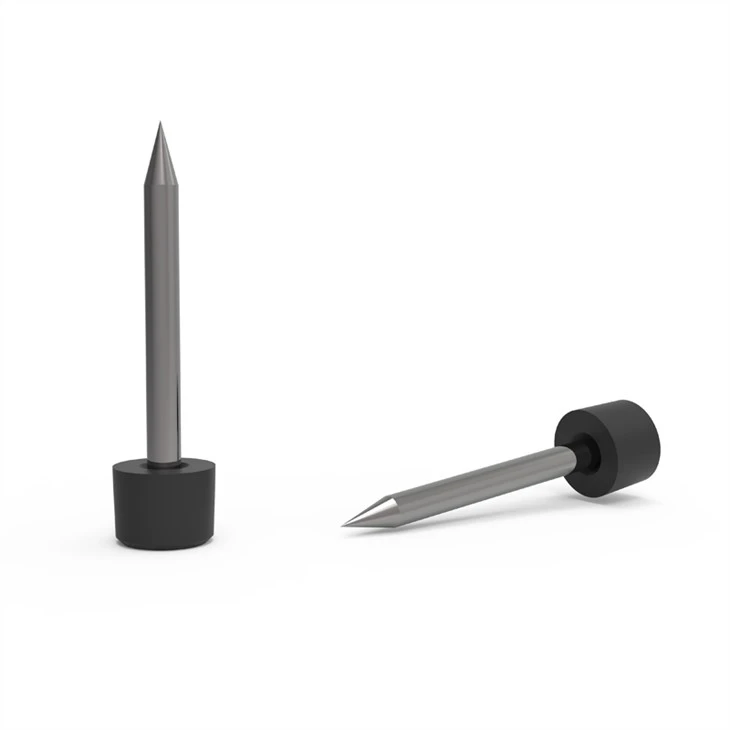
Before starting the detection process, the fiber optic cable needs to be properly prepared. Make sure the ends of the cable are clean and terminated correctly. You may need to use appropriate tools for fiber cutting and termination, such as Fiber Replacement Blade and Conventional Cutter. Any dirt, dust, or damage on the fiber end can affect the accuracy of the Otdr measurements.
Conducting the Otdr Measurement
Setting up the Otdr
Connect the Otdr to the fiber optic cable using a suitable connector. Power on the Otdr and configure the measurement parameters. Set the appropriate wavelength, pulse width, and range according to the length and type of the fiber. A shorter pulse width provides better resolution, which is crucial for detecting micro - bends, while the range should be set to cover the entire length of the fiber being tested.
Taking the Measurement
Once the Otdr is set up, start the measurement process. The Otdr will send a series of light pulses into the fiber and record the reflected signals. The measurement usually takes a few seconds to a few minutes, depending on the length of the fiber and the selected measurement settings. During the measurement, it's important to keep the cable stable to avoid any additional micro - bends or movement - induced errors.
Analyzing the Otdr Trace
Identifying Micro - bends
After the measurement is complete, the Otdr will display a trace on its screen. The trace shows the variation in the backscattered light intensity along the length of the fiber. Micro - bends typically appear as small, sudden dips in the trace, indicating a loss of signal at that specific location. To accurately identify micro - bends, compare the Otdr trace with a baseline trace of a known - good fiber or use the Otdr's built - in event analysis function to mark and measure the loss at each event.

Measuring the Severity of Micro - bends
The severity of a micro - bend can be determined by the amount of signal loss it causes. The Otdr provides information about the loss at each event, usually in decibels (dB). A higher loss value indicates a more severe micro - bend. In general, a loss of more than 0.1dB per micro - bend may require further investigation or repair.
Locating Micro - bends
Once a micro - bend is identified, the Otdr can provide an accurate location of the bend along the fiber. The location is determined based on the time it takes for the reflected light to return from the micro - bend to the Otdr. This information is crucial for technicians to quickly locate and fix the problem. In some cases, additional tools such as visual fault locators may be used to confirm the location of the micro - bend.
Repairing Micro - bends
If a significant micro - bend is detected, it may need to be repaired. The repair process typically involves replacing the damaged section of the fiber or re - routing the cable to eliminate the source of the mechanical stress. After the repair, the fiber should be retested using the Otdr to ensure that the signal loss has been reduced to an acceptable level.
Benefits of Using Otdr for Micro - bend Detection
Using Otdr Equipment for micro - bend detection offers several benefits. Firstly, it provides accurate and reliable information about the location and severity of micro - bends, allowing for targeted repairs. Secondly, it can help prevent potential network failures by detecting micro - bends before they cause significant signal degradation. Finally, regular Otdr testing can extend the lifespan of fiber optic cables by ensuring that they are operating at optimal conditions.
Conclusion
Detecting micro - bends in fiber optic cables is a critical task for maintaining the performance and reliability of fiber optic networks. As an Otdr Equipment supplier, I am committed to providing high - quality equipment and technical support to help you effectively detect and address micro - bends. If you are interested in purchasing Otdr Equipment or have any questions about micro - bend detection, please don't hesitate to contact us for further discussions and procurement negotiations.
References
- "Fiber Optic Test and Measurement" by Peter J. Winzer and R. Ramaswami
- "Optical Time - Domain Reflectometry" in the Handbook of Fiber Optics, edited by M. Shafiul Alam


